
About the company
The company is based on specialists of the highest categories who previously worked at the enterprises of the enterprises of Union Design Bureau Mashproekt, Nikolaev, Motor-sich, Zaporozhye, CIAM.Moscow, Doosan-South Korea and others. These specialists have designed several dozen projects for energy and gas pipeline transport at different times.
As part of the implementation of innovative projects, we have mastered all modern programs for calculating the strength, gorenje, temperature condition, gas dynamics of turbines and compressors. We have developed a technique for improving the geometry of the blades in a three-dimensional formulation, which allowed us to achieve maximum efficiency of individual components and the engine as a whole and confirmed the claimed characteristics in ANSYS and experimentally. We tested the manufacture of most parts using 3D printing (additive method).
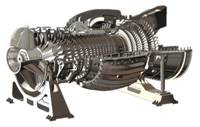
Our developments
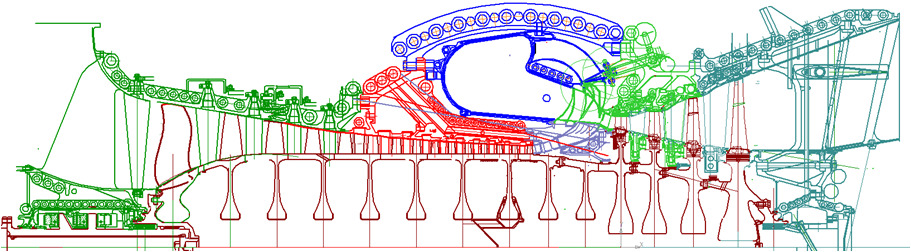
Engines
The engine is 16-25 MW. The long-term (10 years) work on improving the compressor has borne fruit. When the degree of pressure increase is π * k = 25, the efficiency of the compressor is 88%.This is the main contribution to the improvement of the engine (+5% as of today).
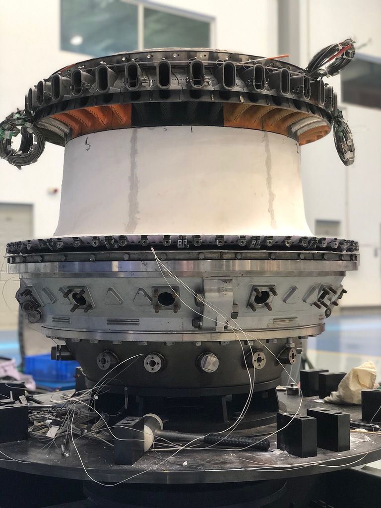
Engines
The engine for a 60 kW regenerated power plant has a fuel consumption one and a half times lower than that of its competitor Capstone, the world's sales leader. This became possible with the additive manufacturing and improvement of all components, but the compressor made the main contribution.
About the project

This engine design can be parameterized into high-power engines. We have maximized the power. The air consumption of 1000 kg/sec provides a power of 400 - 600 MW, depending on the temperature in front of the turbine. In market conditions, the most important indicator of quality is the efficiency of the engine. To surpass analogues, you need to achieve an efficiency of more than 42%. And this will happen if the efficiency of the compressor is 90%, the efficiency of the turbine is 95% and the loss in the combustion chamber is no more than 3.5%. We have set ourselves such a task and solved it."
The design part of the compressor
When calculating the data, we use powerful computing machines and programs (ANSYS) to calculate the flow. It became possible to correctly evaluate the profile, the separate blade grid and the compressor as a whole. Verification calculations of compressors for which experimental characteristics were known showed good convergence. We fixed all the constants and were sure in the calculations of the variants that the change in the result reflected only a change in geometry. More attention was paid to the first stage of the compressor. Optimization calculations have shown that a maximum efficiency of 93% is achieved with a compression ratio of 1.8. The impeller of such a stage has 15 working blades and a sharp rise in the sleeve. The next seven stages are similar to each other and their efficiency is at the level of 94%. The last ninth step is made diagonal. This made it possible to increase its compression ratio and correctly rotate the flow in the radial direction with high efficiency. The entire compressor has an efficiency of 90%. To arrive at this result, calculations of more than a thousand isodromes were performed. Figure 1 shows our engine in comparison. There are 9 stages in the compressor.
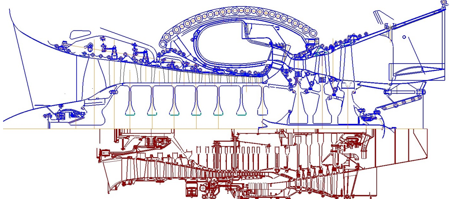
Fig.1 Comparison of 100 MW and 600 MW machines.
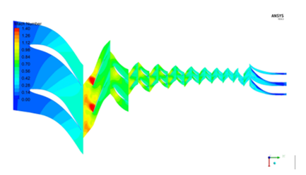
Fig.2 shows the flow pattern in the peripheral section of the compressor.
The design part of the combustion chamber
We propose a new solution (see Figure 3). The chamber was calculated from the working blade of the last stage of the compressor to the working blade of the first stage of the turbine. This eliminated the doubt about the correctness of setting the boundary conditions. Our camera is annular, has a horizontal connector, which ensures the recess of the rotor during repair in operation. The cooling of the heat pipe is provided not by perforation holes, but by a thick layer of a heat-protective coating based on aluminum oxide. This coating for gas turbines is new, but in metallurgical furnaces it has been used for a long time up to 2000 degrees Celsius, at flow rates up to 150 m/sec. The technology of application and repair has been worked out. We tested the coating in harsh conditions and were satisfied with the result. These design solutions made it possible to reduce the total pressure loss to 4.5% and practically eliminated the formation of nitrogen oxides. The air after the last stage of the compressor is collected into the nozzles for passage through the nozzle blades and cools them. After the nozzle blades, air enters the mixers and fuel is supplied to them. After the mixers, the oxidizer excess coefficient is not less than 2 and the temperature in the combustion zone is not more than 1600 K. Gorenje Nitrogen oxides are not formed in this case. The air velocity in the mixer is more than 100 m/sec, which eliminates the backflash of the flame.
The volume of the combustion zone is increased and the flow rates of the poor mixture and combustion products do not exceed 30 m/sec. Gorenje The poor mixture comes from the mixer to the left, and in the gorenje it turns and flows to the right. Gorenje's stay in the burning zone is an order of magnitude longer than usual. Good mixing ensures a low temperature in the combustion zone and, as a result, the absence of nitrogen oxides. Gorenje Figures 4 and 5 show the mixing and combustion in CS. Gorenje. No additional regulation is required to ensure environmental performance.
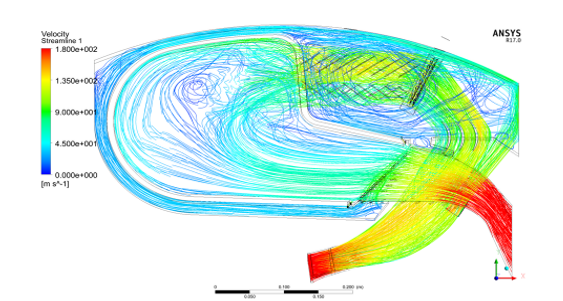
Fig.3 Flow of the working fluid in the combustion chamber
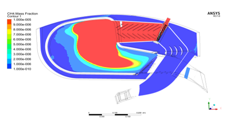
Fig. 4 Gorenje methane.
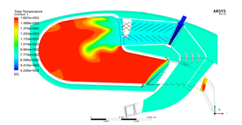
Fig.5 Temperature field in the combustion chamber.
The design part of the turbine
The calculation in ANSYS confirmed the efficiency in the region of 94%. There is a lot of cooling air and irrational blowing it into the flow part. In the root section, local diffusivity leads to acceleration above the speed of sound, and closing jumps dampen the speed. Problem solving: Firstly, leaks through labyrinth seals and through radial gaps remained unchanged in absolute terms, but their share fell significantly with an increase in total consumption. Secondly, additive manufacturing has improved cooling efficiency by reducing cooling air consumption. Figure 6 shows the cooling of the working blade of the first stage
The arrangement of the channels guarantees good cooling of the profile surface and the shelf. The temperature gradients along the wall thickness are reduced by 2-3 times. Similarly, thermal stresses have been reduced and, accordingly, the safety margins and service life have been increased. As a result, 3% of the air was spent on cooling after the compressor and 2% after the fifth stage, In the third, the height gradient was reduced. The first stage is made gradient-free. The flow part is formed by rectilinear generators parallel to the velocity vector in the throat of the nozzle apparatus. Therefore, the current lines after the throat are straight and parallel.Figure 7 illustrates this.
In the second stage, the height gradient is reduced, and in the third it is still essential to ensure axial output The output diffuser is designed taking into account the velocity field behind the third stage and effectively reduces the output speed (see Fig.9).
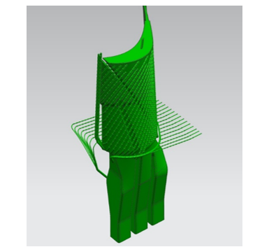
Fig.6 Cooling of the working blade of the first stage.
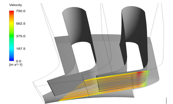
Fig.7 Current lines after the first nozzle unit
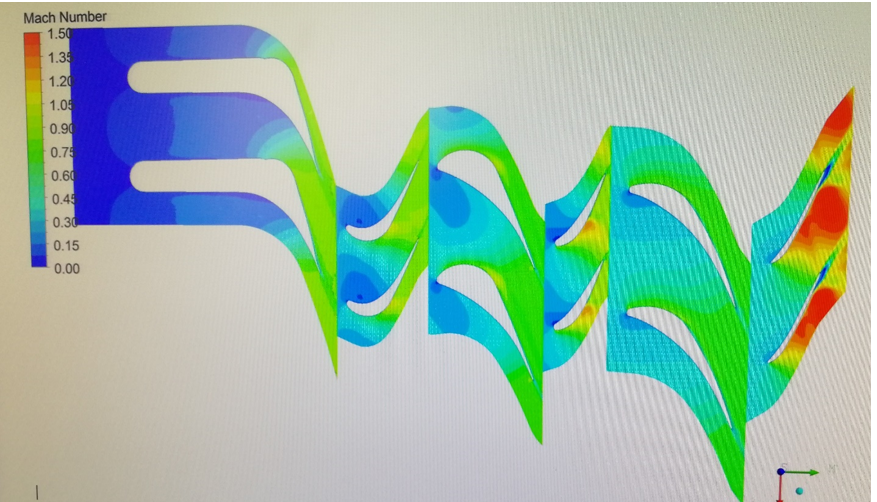
Fig.8 Visualization of Mach numbers in the peripheral section of the turbine.
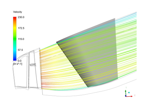
Fig.9 Output diffuser
Manufacturing technology
Traditional manufacturing technologies are widely represented in our project. These are discs and the rotor as a whole, simple housings. There are no competitive new technologies for them. In the design of the combustion chamber and turbine, we provided for the manufacture of parts in an additive manner and tested the manufacture on a scale of 0.25. Figures 10, 11 and 12 show these parts and assemblies.
The presented cooled blades are manufactured in the traditional way. Additive technologies make it much easier to deal with this. We have developed a roadmap for finishing works based on the use of 0.25 scale models, which allows us to reduce costs by 50 times and reduce the time of these works by three times.
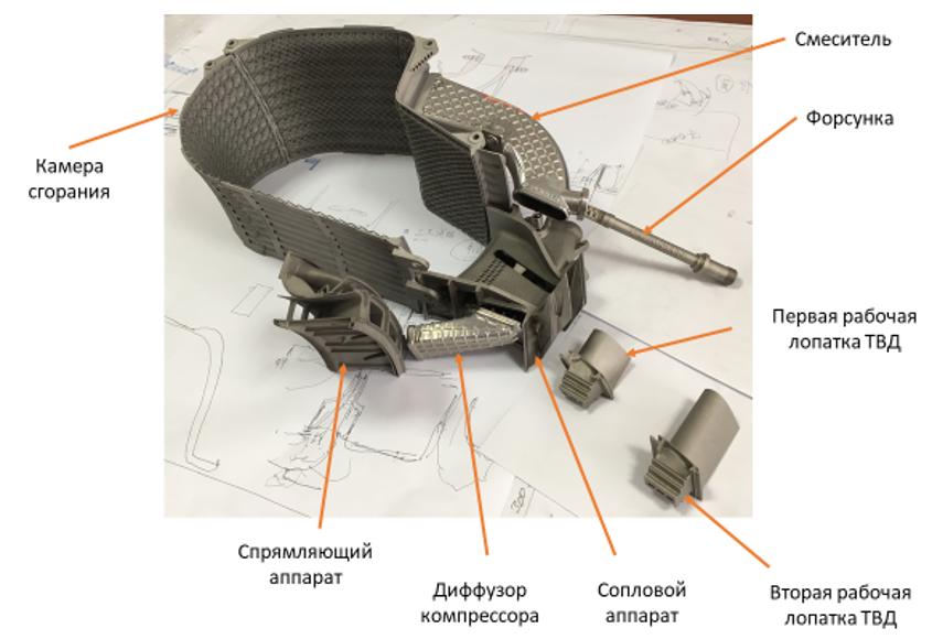
Fig.10 Details of the hot path.
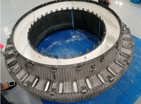
Fig.11 The heat pipe.
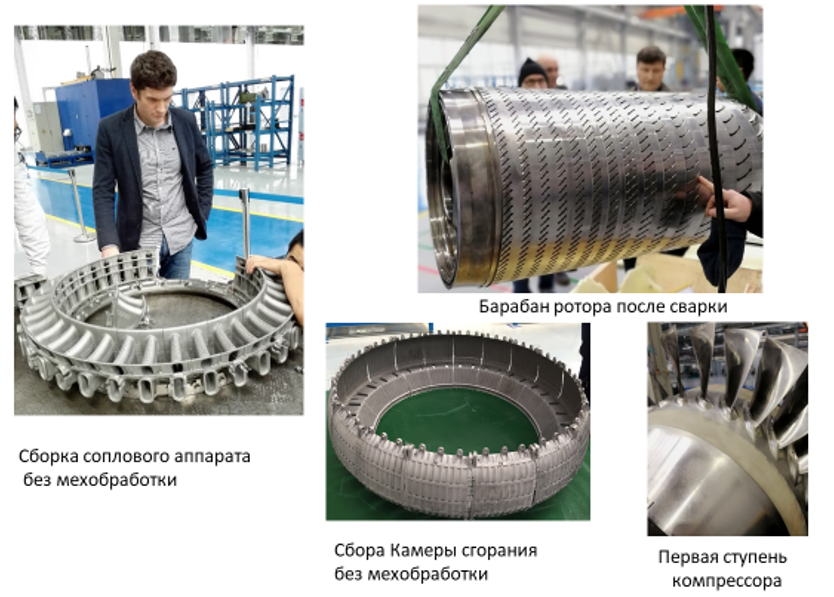
Fig.12 shows the flow pattern in the peripheral section of the compressor.
Our technologies allow us to
1
It represents a gas turbine engine with a capacity from 16 to 600 MW with an efficiency of 43-45%;
2
The documentation is ready for the production of a prototype;
3
The project makes it possible to create a gas turbine engine for energy and gas transportation in a short time and at the lowest cost, competitive in the global market;